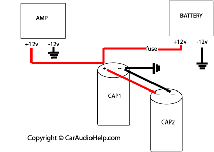
Note that the two terminals do not both connect to the +12 volt power wire. This will cause your amplifier's power supply to be cut off. The power capacitor acts like a small battery (power storage) so it is connected as shown in the diagram. The downside of this type of connection is you don't know if the power capacitor fails since the amplifier will continue to work with or without a working power capacitor.
Ideally the power capacitor should be as close as possible to the amplifier. Within a couple of feet is acceptable. This keeps any cable losses to a minimum.
Here's how to wire two capacitors in a system. In the diagram both capacitors have their ground terminals wired together but you could also ground them independently. You can even fabricate or purchase "buss bars" which are solid pieces of metal that connect the capacitors both physically and electrically. These "buss bars" are generally bare metal so they can be dangerous if not installed properly. Use caution if you take this route.

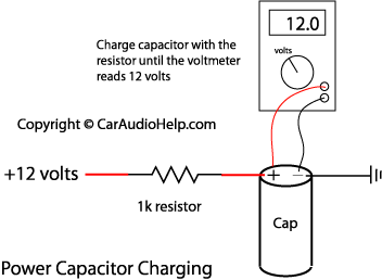
NOTE OF CAUTION: Power capacitors store a large amount of energy and they charge very quickly. You must first "charge" your power capacitor before connecting it directly to +12 volts. This is done with the a 1k ohm resistor and a voltmeter. The exact value of the resistor is not critical but I would keep it in the 500-1k ohm range. I would recommend getting a 1 watt resistor if possible (your capacitor may have come with a resistor for charging). A lower wattage resistor will heat up too quickly. Also, do not hold the resistor with your bare hand. The current flowing through the resistor will cause the resistor to heat up and you could be burned. A good place to put the resistor is in the main power wire fuse holder (the one installed near the battery). Simply substitute the resistor for the fuse. A diagram for the capacitor charging setup is shown below.
You will need to place a voltmeter across the capacitor to monitor the voltage. Once the voltmeter reads 12 volts you can remove the voltmeter and replace the resistor with the power fuse. Alternatively you can measure the voltage across the charging resistor. It should start around 12 volts and slowly work its way down to 0 volts. When the voltage stops changing you have charged the capacitor completely.
Another method for charging involves using an old style test light instead of a resistor. The connection is similar but you don't need a voltmeter to monitor voltage. When the bulb goes out the capacitor is charged (because the voltage across the bulb went from 12volts to 0volts).


